
What Is Zero MOQ Turnkey Prototype PCBA? (Architecture & Scope)
A zero MOQ prototype turnkey PCBA service delivers fully assembled circuit boards from 1 to 5 units without setup penalties or minimum batch constraints. The turnkey model unifies bare board fabrication, active bill-of-materials procurement, surface mount assembly, and automated testing under a single contract manufacturer. Hardware engineering teams frequently face unnecessary friction when managing fragmented suppliers. Sourcing bare boards from one fabricator, buying passives from multiple distributors, and sending kits to a consignment assembly house adds administrative overhead and stretches validation cycles by weeks. Opting for a comprehensive turnkey PCB assembly workflow shifts the entire supply chain risk to your electronics manufacturing partner. Full-turnkey prototype execution eliminates component loss during kitting, optimizes line setup times, and guarantees engineering accountability across every solder joint.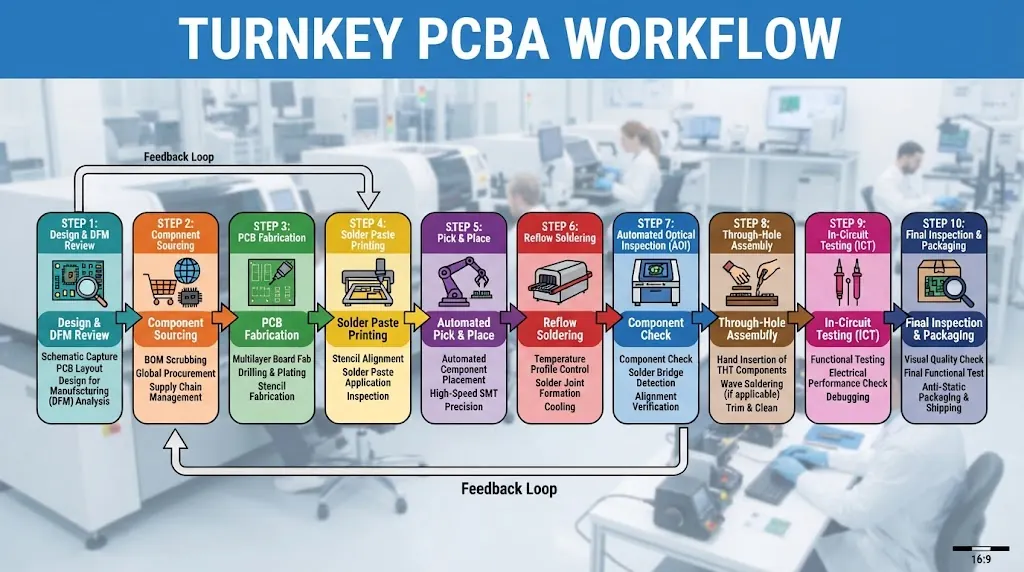
Turnkey PCBA Scope: An end-to-end manufacturing agreement where the EMS provider fabricates the bare board, procures 100% of the active/passive electronic components, populates the substrate via automated SMT/THT lines, and inspects the final assembly according to IPC-A-610 Class 2 or Class 3 standards.When requesting a prototype PCBA quotation, working with a zero-MOQ manufacturer guarantees that non-recurring engineering (NRE) charges, laser stencils, and tooling costs remain cost-effective even for a single validation board.
Essential Engineering Files Required for a Fast Turnkey PCBA Quotation
Quotation delays almost always stem from incomplete file packages or ambiguous component data. Providing clean, production-ready engineering documentation allows EMS quoting engines to generate exact material and labor costs within 2 to 24 hours.Gerber, ODB++, and CAD Fabrication Data
Bare board fabrication pricing depends on substrate complexity, copper weight, layer counts, and dielectric stackup requirements. Ensure your export archive includes standard RS-274X, Gerber X2, or native ODB++ datasets along with NC drill files.- Layer Stackup Details: Dielectric core thicknesses, prepreg types, and target impedance lines (e.g., 50Ω single-ended, 90Ω/100Ω differential).
- Mechanical Fabrication Drawings: Board outline dimensions, routing tolerances, internal cutouts, v-scoring, and mouse-bite breakout tabs.
- Finishing Specifications: Surface finishes such as Electroless Nickel Immersion Gold (ENIG), Lead-Free HASL, or OSP, alongside soldermask and silkscreen colors.
Hierarchical BOM Formatting, MPN Precision & Alternate Sourcing
The Bill of Materials (BOM) drives the majority of the prototype cost. Quoting algorithms parse Manufacturer Part Numbers (MPNs) against real-time distributor APIs to retrieve live stock and tier pricing. To avoid engineering holds during pricing, format your spreadsheet with designated columns: Reference Designator, Exact MPN, Component Manufacturer, Package/Footprint, and Description. Adding pre-approved Form-Fit-Function (FFF) alternate parts prevents procurement bottlenecks for tight-allocation ICs.Centroid (XYRS) Data and Assembly Drawings
Surface mount pick-and-place systems rely on the Centroid (also referred to as the XY data or pick-and-place file) to position components. This file must contain the Reference Designator, X and Y coordinates (in mm or mils), board side (Top/Bottom), and rotational angle (0° to 359°).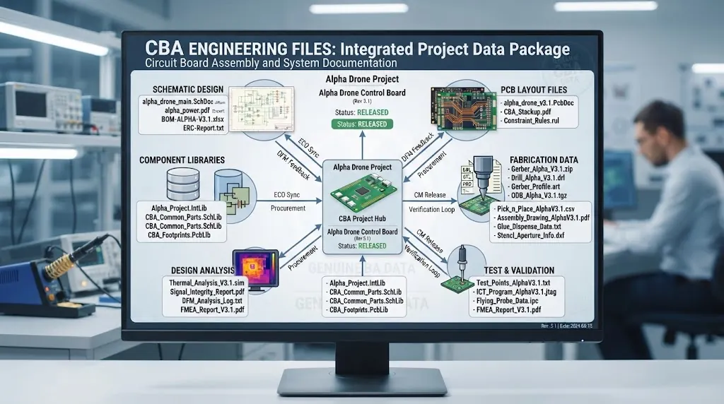
| File Type | Standard Format | Required Contents | Impact on Turnaround |
|---|---|---|---|
| PCB Fabrication Data | Gerber RS-274X / ODB++ | Copper, mask, silkscreen, drill files | Calculates substrate yield and layer counts |
| Bill of Materials | .XLSX, .CSV | MPN, RefDes, Footprint, Approved Alternates | Drives real-time component availability checks |
| Centroid / Placement | .TXT, .CSV | RefDes, Layer, X/Y Coordinates, Rotation | Programs high-speed SMT pick-and-place lines |
| Assembly Drawings | Pin 1 indicators, polarities, mechanical hardware | Prevents post-reflow orientation errors |
Turnkey Prototype PCBA Cost Breakdown: Understanding Key Price Drivers
For low-quantity runs (1 to 10 boards), per-unit costs are heavily weighted toward machine setup and procurement overhead rather than raw mass-production silicon pricing. Understanding these cost drivers helps hardware designers optimize their prototypes for manufacturability.- SMT Stencil Tooling & Line Calibration: High-precision stainless steel laser stencils (electro-polished for fine-pitch QFNs and 0.4mm pitch BGAs) represent a fixed upfront NRE charge.
- Component Minimum Packaging Surcharges: Franchised distributors often impose minimum order quantities or cut-tape handling fees for small batch purchases.
- Substrate Technology: High-Density Interconnect (HDI) microvias, blind/buried vias, and high-frequency materials like Rogers or Teflon increase base fabrication costs by 40% to 150% over standard FR-4.
- Assembly Complexity: Double-sided SMT placement requiring dual reflow passes, selective through-hole soldering, and epoxy underfill for delicate BGAs adds manual intervention and specialized machine time.
The Visianda Agile-NPI™ Protocol: From Zero MOQ Quote to First Article in 72 Hours
To eliminate quotation bottlenecks and deliver zero-defect prototypes rapidly, Visianda EMS developed a proprietary engineering framework designed specifically for new product introduction. The Visianda Agile-NPI™ Protocol is a standardized four-stage validation methodology that automates BOM scrubbing, identifies component obsolescence, verifies thermal reflow profiles, and conducts automated optical verification before releasing a prototype batch to the production floor.
Stage 1: Algorithmic BOM Scrubbing & Supply Verification
The system scans BOM files via real-time authorized distributor APIs. It flags non-stocked lines, End-of-Life (EOL) parts, and unverified packages within minutes, suggesting drop-in alternates instantly.
Stage 2: Comprehensive DFM/DFA Clearance Check
Engineering teams review annular ring clearances, solder dam widths, component spacing, and copper balance to prevent tombstoning, bridging, or thermal dissipation imbalances during reflow.
Stage 3: Dynamic SMT Line Setup & Stencil Optimization
Laser stencils are cut with specialized aperture reductions (such as home-plate or cross-hatch profiles) tailored for challenging components like QFN ground pads and 0201 passives.
Stage 4: Automated First Article Inspection (FAI)
The first board off the SMT line undergoes automated LCR testing, 3D AOI, and high-resolution 3D X-Ray (AXI) to inspect BGA solder joint wetting and ball voiding before running the remaining prototype units.
The Visianda Agile-NPI™ Protocol is a standardized four-stage validation methodology that automates BOM scrubbing, identifies component obsolescence, verifies thermal reflow profiles, and conducts automated optical verification before releasing a prototype batch to the production floor.
Stage 1: Algorithmic BOM Scrubbing & Supply Verification
The system scans BOM files via real-time authorized distributor APIs. It flags non-stocked lines, End-of-Life (EOL) parts, and unverified packages within minutes, suggesting drop-in alternates instantly.
Stage 2: Comprehensive DFM/DFA Clearance Check
Engineering teams review annular ring clearances, solder dam widths, component spacing, and copper balance to prevent tombstoning, bridging, or thermal dissipation imbalances during reflow.
Stage 3: Dynamic SMT Line Setup & Stencil Optimization
Laser stencils are cut with specialized aperture reductions (such as home-plate or cross-hatch profiles) tailored for challenging components like QFN ground pads and 0201 passives.
Stage 4: Automated First Article Inspection (FAI)
The first board off the SMT line undergoes automated LCR testing, 3D AOI, and high-resolution 3D X-Ray (AXI) to inspect BGA solder joint wetting and ball voiding before running the remaining prototype units.
Lead Time Optimization: Mitigating Supply Chain Delays in Fast-Turn Prototypes
Prototype lead times are primarily dictated by component procurement windows rather than manufacturing hours. While bare board fabrication and SMT placement take as little as 24 to 48 hours, extended lead-time microcontrollers or specialized passives can stall an entire build. In our manufacturing experience across medical and automotive NPI programs, pre-sourcing authorization provides the greatest schedule compression. Approving authorized alternates in the initial quotation phase eliminates multi-day holds when a primary MPN is out of stock. Visianda EMS maintains strategic stocking partnerships with franchised global distributors—including Digi-Key, Mouser, Arrow, and Avnet—enabling 24-hour component delivery directly to our assembly cells while adhering to strict ISO 9001 and ISO 13485 anti-counterfeit mitigation procedures.Quality Assurance & Value-Added Prototype Testing: ISP, Functional Test & AOI
Building zero MOQ prototypes does not mean bypassing industrial quality verification. Single-board validation builds require rigorous testing so hardware engineers can focus purely on firmware and logic debugging rather than hardware assembly flaws.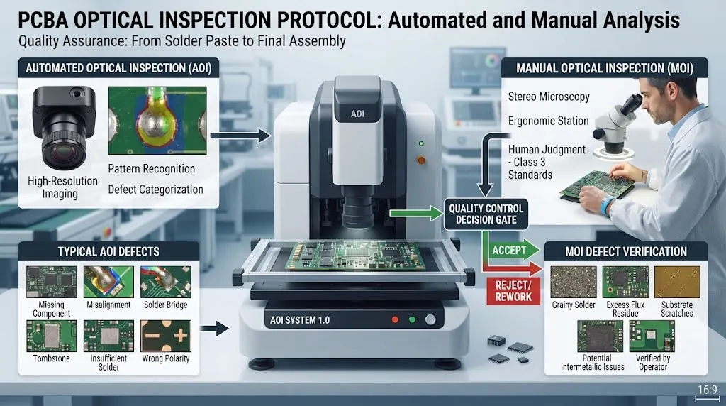
- 3D Automated Optical Inspection (AOI): Validates component presence, orientation, polarity markings, solder fillet heights, and identifies bridging or tombstoning across 01005 passives and fine-pitch ICs.
- 3D X-Ray Inspection (AXI): Essential for non-visible solder joints, such as Ball Grid Arrays (BGAs), Quad Flat No-leads (QFNs), and land grid packages. It calculates solder void percentages against IPC-A-610 Class 3 standards (typically <15% voiding).
- In-System Programming (ISP) & Boundary Scan: Pre-flashing bootloaders and microcode via dedicated JTAG, SWD, or UART headers ensures every processor boots before leaving the manufacturing floor.
- Functional Circuit Testing (FCT): Custom test jigs and bed-of-nails fixtures verify operational voltages, power rail sequencing, signal integrity, and digital I/O responsiveness.
Seamless Prototype-to-Volume Scaling with Visianda EMS
Scaling from an initial 5-piece functional prototype to medium- or high-volume production often introduces unforeseen assembly challenges if design continuity is broken between different facilities. Visianda EMS bridges this gap by utilizing the same MES data, feeder setups, and reflow profile calibrations from the prototype stage to ramp directly into Low-Rate Initial Production (LRIP) and high-volume manufacturing. When you are ready to launch your next hardware revision or validate a new architecture, request a custom PCBA quote for instant DFM analysis and competitive zero-MOQ turnkey pricing.Frequently Asked Questions (FAQ) About Zero MOQ Turnkey PCBA Quotes
Can I order exactly 1 piece for a prototype PCBA turnkey service?
Yes. Zero MOQ means there is no minimum unit restriction. You can order 1, 3, or 5 functional boards for engineering verification without paying arbitrary minimum batch fees.How fast can I receive a complete turnkey quotation?
When complete Gerber files, Centroid data, and a clean BOM with exact MPNs are submitted, quotation turnarounds typically range from 2 to 24 hours depending on component complexity and sourcing requirements.How does Visianda prevent counterfeit or gray-market components?
Visianda EMS procures components exclusively through franchised, authorized distributors and factory-direct channels. Every received component batch is verified with incoming visual inspection, lot code traceability, and packaging verification under ISO 9001 quality controls.Do I need to supply components in full reels for prototype assembly?
No. For turnkey prototype orders, our procurement team sources components in cut tape, continuous tape, tube, or tray packaging. Our modern high-speed SMT pick-and-place lines feature dynamic strip feeders optimized for small-batch prototyping.Is my intellectual property and firmware secure during testing?
Visianda EMS enforces strict non-disclosure agreements (NDAs) and utilizes air-gapped programming stations for In-System Programming (ISP) to protect proprietary firmware, schematics, and manufacturing files.Accelerate Your Hardware Development Cycle
Get your zero MOQ prototype turnkey PCBA quotation today. Fast 24-hour DFM analysis, 100% authorized component sourcing, and precision IPC Class 2/3 assembly from Visianda EMS.
Upload Your RFQ Package