
Visianda manufactures aluminum-base PCBs (MCPCB) for LED lighting, power electronics, and any application where thermal management is a primary design constraint. Our aluminum PCBs use high-thermal-conductivity dielectric layers to transfer heat from components directly to the aluminum substrate.
What Is an Aluminum PCB?
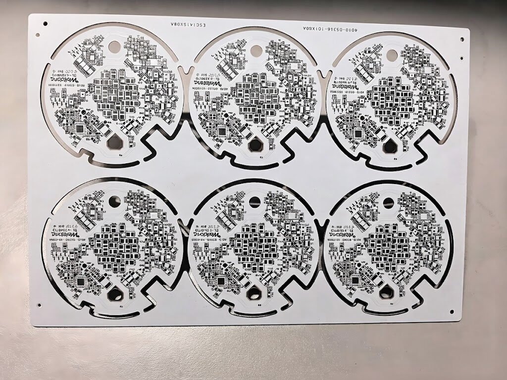
An aluminum PCB (also called MCPCB — metal core PCB) consists of a copper circuit layer, a thermally conductive dielectric layer, and an aluminum base substrate. The dielectric layer provides electrical isolation while conducting heat from the circuit layer to the aluminum base, which acts as a heat spreader.
Standard FR4 PCBs have thermal conductivity of approximately 0.3 W/m·K. Aluminum PCBs achieve 1.0–3.0 W/m·K, enabling 5–10× better heat dissipation. This allows higher power density, longer component lifetime, and elimination of external heatsinks in many applications.
Visianda manufactures single-sided and double-sided aluminum PCBs with dielectric thermal conductivity options from 1.0 W/m·K (standard) to 3.0 W/m·K (high-performance). We also offer copper-base MCPCBs for applications requiring maximum thermal performance.
Technical Specifications
Key Advantages
Superior Heat Dissipation
1.0–3.0 W/m·K thermal conductivity — up to 10× better than standard FR4 for high-power LED and power electronics.
Extended Component Lifetime
Lower junction temperatures directly extend LED and power device lifetime, reducing warranty costs.
Eliminates External Heatsinks
The aluminum base acts as an integrated heatsink, simplifying mechanical design and reducing BOM cost.
Dimensional Stability
Aluminum substrate provides excellent flatness and rigidity, important for LED arrays requiring precise optical alignment.
RoHS Compliant
All materials and surface finishes are RoHS 2.0 compliant for global market access.
High Voltage Isolation
Dielectric layer provides 2500V+ isolation between circuit and aluminum base for safety-critical applications.
Where It's Used
LED Lighting
Street lights, high-bay fixtures, grow lights, automotive headlights
Power Electronics
Motor drives, DC-DC converters, inverters
Automotive
LED headlights, taillights, interior lighting
Industrial
Solid-state relays, power supplies, UPS systems
Consumer Electronics
LED backlights, projectors, gaming peripherals
Renewable Energy
Solar inverters, EV charging stations
Medical
Surgical lighting, phototherapy equipment
Telecom
Base station power amplifiers, RF power modules
Why Choose Visianda for Aluminum PCB?
- Thermal conductivity options from 1.0 to 3.0 W/m·K — matched to your power density requirements
- Copper-base MCPCB available for maximum thermal performance applications
- Full turnkey service: aluminum PCB fabrication + LED/component assembly in one order
- IPC-A-610 inspection for solder joint quality on aluminum substrate
- Free thermal simulation consultation for high-power LED array designs
- RoHS 2.0 and REACH compliant materials — documentation provided
Frequently Asked Questions
What thermal conductivity do I need for my LED application?
For most commercial LED lighting applications (< 5W per LED), 1.0–1.5 W/m·K is sufficient. For high-power LEDs (5–20W per device) or dense arrays, 2.0 W/m·K is recommended. For automotive headlights and industrial high-bay fixtures, 3.0 W/m·K provides the best thermal performance. We can provide thermal simulation to help select the right specification.
Can you assemble LEDs and other components on aluminum PCBs?
Yes. We offer full turnkey assembly on aluminum PCBs, including SMT LED placement, reflow soldering, and functional testing. We use custom reflow profiles optimized for aluminum substrate to prevent warpage.
What is the maximum copper weight available?
We offer 1 oz, 2 oz, and 3 oz copper on aluminum PCBs. Heavier copper weights improve current-carrying capacity and thermal spreading but require wider trace widths to maintain etching accuracy.
Do you offer copper-base MCPCBs?
Yes. Copper-base MCPCBs provide higher thermal conductivity than aluminum (385 W/m·K vs. 160 W/m·K for aluminum) and are recommended for applications with very high power density. Lead time is typically 2–3 days longer than aluminum-base boards.
Related PCB & PCBA Types
200W High-Bay LED Driver on 2.0 W/m·K Aluminum PCB
A Dutch LED lighting manufacturer developing a 200W high-bay luminaire for industrial warehouse applications — requiring a 300mm × 200mm aluminum PCB to mount 40 × 5W Cree XHP50.3 LEDs.
The Problem
The customer's initial design used 1.0 W/m·K aluminum PCBs from a local European supplier. Thermal imaging during life testing showed LED junction temperatures of 92°C at 25°C ambient — 17°C above the 75°C target. At this junction temperature, the L70 lifetime (time to 70% lumen maintenance) was only 28,000 hours, well below the 50,000-hour specification.
Key Challenges
- 40 × 5W LEDs (200W total) on a 300mm × 200mm board — 3.3 W/cm² power density
- Target LED junction temperature ≤75°C at 25°C ambient with natural convection only
- Board flatness ≤0.3mm over 300mm length — critical for optical alignment of secondary lenses
- 3 oz copper required for 10A bus bars connecting LED strings
- CE and UL certification requirements — dielectric voltage withstand ≥3750V
Our Solution
We recommended upgrading to 2.0 W/m·K dielectric with 3 oz copper and a 3.0mm aluminum base (vs. the customer's original 1.6mm). The thicker aluminum base improves lateral heat spreading, reducing the thermal resistance from LED junction to ambient by 23% compared to the original design. We also optimized the copper pour layout to create a continuous thermal spreading layer under the LED pads, connecting all LED thermal pads to the aluminum base through the minimum dielectric thickness. The 3 oz copper bus bars were routed to minimize current crowding at the LED string connections. All boards were tested for dielectric withstand at 4000V for 60 seconds before shipment.
Results & Outcomes
"Switching to Visianda's 2.0 W/m·K aluminum PCB solved our thermal problem without requiring any changes to the mechanical design. The thermal simulation they provided before we placed the order accurately predicted the junction temperature we measured in testing."
Thermal Engineer, LED Lighting Manufacturer — Eindhoven, Netherlands