
Visianda manufactures high frequency PCBs on Rogers, PTFE, and ceramic-filled laminates for RF, microwave, and millimeter-wave applications. Our precision etching and controlled impedance process delivers consistent electrical performance for antenna, radar, and wireless communication designs.
What Is a High Frequency PCB?
High frequency PCBs are manufactured on low-loss dielectric materials specifically engineered for RF and microwave applications. Standard FR4 exhibits high dielectric loss (Df > 0.02) and significant Dk variation with frequency, making it unsuitable for signals above approximately 1 GHz where signal integrity is critical.
High frequency laminates such as Rogers 4350B (Dk 3.48, Df 0.0037) and Rogers 5880 (Dk 2.20, Df 0.0009) maintain stable electrical properties across a wide frequency range, enabling predictable impedance and minimal signal loss in antenna feed networks, power amplifiers, and radar front-ends.
Visianda's high frequency PCB process uses dedicated tooling and etching chemistry for PTFE-based materials, which require different handling than standard FR4. Our precision CNC routing and controlled etching achieve trace width tolerances of ±0.015mm on high frequency laminates.
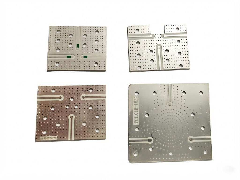
Technical Specifications
Key Advantages
Low Dielectric Loss
Rogers and PTFE materials minimize insertion loss at GHz frequencies — critical for PA efficiency and receiver sensitivity.
Stable Dk vs. Frequency
Consistent dielectric constant from 1 MHz to 77 GHz ensures predictable impedance across the operating band.
Precision Impedance Control
±8% impedance tolerance on microstrip and stripline structures, verified by TDR on every panel.
Low CTE for Reliability
Rogers laminates have lower Z-axis CTE than FR4, reducing via barrel stress in thermal cycling.
Hybrid Stackup Capability
Rogers RF layers can be combined with FR4 digital layers in a single multilayer board for mixed-signal designs.
mmWave Capability
Process-qualified for 24 GHz, 60 GHz, and 77 GHz radar applications on Rogers 5880 and RO3003.
Where It's Used
5G / Telecom
Massive MIMO antennas, base station PA boards
Automotive Radar
77 GHz ADAS radar front-ends, blind spot detection
Satellite
Ku/Ka-band LNBs, phased array antennas
Defense
EW systems, radar receivers, secure comms
IoT / Wireless
Wi-Fi 6E, UWB, sub-6GHz 5G modules
Medical
Microwave ablation, imaging systems
Test & Measurement
VNA calibration standards, RF probes
Industrial
Level sensors, flow meters, process radar
Why Choose Visianda for High Frequency?
- Dedicated PTFE/Rogers processing line — no cross-contamination with standard FR4 process
- TDR impedance verification on every panel with measurement report included
- Hybrid Rogers/FR4 stackup capability for mixed RF-digital designs
- Immersion silver and hard gold finish options for low-loss RF contact surfaces
- Engineering consultation on material selection, stackup, and trace geometry
- mmWave process qualification up to 77 GHz on Rogers 5880 and RO3003G2
Frequently Asked Questions
Which Rogers material should I use for my application?
Rogers 4350B (Dk 3.48) is the most common choice for 5G, Wi-Fi, and general RF applications up to 30 GHz. Rogers 5880 (Dk 2.20) is preferred for mmWave and satellite applications where minimum loss is critical. We provide free material selection consultation as part of the quoting process.
Can you combine Rogers and FR4 in the same board?
Yes. We regularly manufacture hybrid stackups with Rogers RF layers and FR4 digital layers. The key challenge is managing the CTE mismatch during lamination — our process engineering team has developed a validated lamination cycle for the most common hybrid combinations.
What surface finish is best for RF applications?
Immersion silver (ImAg) is generally preferred for RF applications due to its excellent conductivity and flat surface. ENIG is also widely used. Hard gold is recommended for connector contact areas. We advise against HASL on high-frequency boards due to surface roughness effects at GHz frequencies.
Do you provide TDR measurement reports?
Yes. TDR impedance measurement reports are included with every high frequency PCB order at no additional charge. Reports include measured impedance values for all controlled impedance structures and comparison against the specified target.
Related PCB & PCBA Types
77 GHz ADAS Radar Front-End PCB on Rogers RO3003G2
A Tier-1 automotive supplier developing a 77 GHz short-range radar module for blind-spot detection and rear cross-traffic alert — targeting IATF 16949-aligned production for a European OEM program.
The Problem
The customer's initial prototype boards on Rogers RO3003 (original formulation) showed insertion loss 2.3 dB higher than simulation at 77 GHz, traced to surface roughness of the copper foil exceeding the skin depth at millimeter-wave frequencies. The issue was not caught until system-level RF testing, requiring a material change late in the development cycle.
Key Challenges
- 77 GHz operation requires copper surface roughness Rz < 1.0 μm to minimize conductor loss
- Rogers RO3003G2 (low-profile copper) required process qualification — new material for our line
- Trace width tolerance ±0.010mm required for 50Ω microstrip at 77 GHz on 0.127mm substrate
- IATF 16949-aligned documentation package required for automotive program qualification
- 8-week timeline from material qualification to first article approval
Our Solution
We qualified Rogers RO3003G2 with low-profile (LP) copper foil, which reduces surface roughness from Rz ~3.0 μm (standard foil) to Rz ~0.8 μm — below the skin depth at 77 GHz. The qualification included a full process FMEA, control plan, and measurement system analysis (MSA) for the critical trace width and impedance characteristics. We implemented a dedicated etch chemistry formulation for the ultra-thin 0.127mm substrate to prevent board warpage during processing. Impedance coupons were placed at 12 locations per panel (vs. standard 4) to characterize within-panel variation. All process parameters were documented in an APQP-style quality plan for the customer's supplier qualification file.
Results & Outcomes
"The material qualification was completed faster than we expected, and the process documentation was thorough enough to pass our OEM's supplier audit without any corrective actions. Visianda is now our qualified source for all mmWave radar PCBs."
RF Design Manager, Automotive Radar Supplier — Stuttgart, Germany