
Mixed-Technology PCBA Quoting Framework: The 4 Core Evaluation Dimensions
Securing an accurate, rapid turnaround quote for mixed Surface Mount Technology (SMT) and Dual In-line Package (DIP) through-hole assemblies requires a synchronized engineering audit of board geometry, solder deposition chemistry, and supply-chain bill of materials (BOM) validation. A complete technical RFQ submission eliminates front-end engineering questions (EQs) and prevents sudden cost adjustments caused by unflagged thermal mismatches or manual through-hole soldering steps. Mixed-technology assemblies present unique assembly friction points because they pair high-speed automated pick-and-place lines with secondary through-hole soldering steps. Evaluating these boards requires assessing four distinct vectors before releasing an assembly to the shop floor:- Engineering File Completeness: Clean RS-274X, ODB++, or IPC-2581 files paired with Centroid data to eliminate coordinate drift.
- Process Flow Alignment: Determining whether DIP parts should undergo selective wave soldering, custom wave solder masking pallets, or targeted hand assembly.
- Upfront Manufacturing Scrubbing: Executing a comprehensive DFM engineering review before bare PCB fabrication to verify hole-to-lead aspect ratios and component shadow zones.
- Component Integrity & Sourcing Traceability: Real-time validation of active Manufacturer Part Numbers (MPNs) against franchised supply chains to avoid line stoppages.
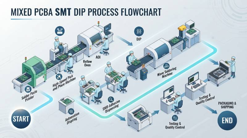
"In our assembly lines, over 68% of mixed-assembly quoting delays stem from missing mechanical clearance rules for through-hole pin tails and omitted lead diameters in the initial BOM."
Essential Engineering File Package for Zero-Delay Mixed SMT & DIP Quotes
An incomplete data package stalls quoting queues. To secure a firm quotation within 2 hours, your engineering package must include standardized design files and precise component location mappings.Required Documentation Checklist
- Gerber RS-274X, ODB++, or IPC-2581: Complete Gerber archives must contain copper layers, solder mask, silkscreen, paste layers (top and bottom), and NC drill files with defined plated through-hole (PTH) and non-plated through-hole (NPTH) attributes.
- Structured BOM (.xlsx or .csv): A clean bill of materials detailing Line Item Number, Reference Designator (e.g., R1, C4, U2, J1), Component Quantity, Primary Manufacturer Part Number (MPN), Primary Manufacturer Name, Approved Alternate MPNs, Package/Footprint Designation, and Mounting Type (SMT vs. DIP/PTH).
- Centroid / Pick-and-Place (CPL) Data: ASCII text or CSV files specifying Reference Designator, Board Surface Layer (Top/Bottom), X-coordinate, Y-coordinate, and Component Rotation (0° to 359° per IPC Standards rules).
- Mechanical Assembly & DIP Detail Drawings: Explicit callouts for maximum component height, through-hole lead clinch angles, lead trim lengths (typically 1.5 mm ± 0.5 mm), and keep-out constraints for connectors.

| Item # | Ref Des | Qty | Primary MPN | Manufacturer | Mounting | Package | Approved Alternate |
|---|---|---|---|---|---|---|---|
| 1 | C1, C2 | 2 | GRM155R71C104KA88D | Murata | SMT | 0402 | CL05B104KO5NNNC |
| 2 | U1 | 1 | STM32F407VGT6 | STMicroelectronics | SMT | LQFP-100 | None (Critical IC) |
| 3 | J1 | 1 | 691214110002 | Wurth Elektronik | DIP/PTH | 5.0mm Pitch | OSTTC022162 |
Critical Cost Drivers in Mixed Assembly: SMT Pitch, DIP Soldering Methods, and Substrates
Mixed PCBA costs are driven by package miniaturization, thermal density, and through-hole post-processing methods. Managing these variables during design helps control prototype budgets and production overhead. When pairing high-density SMT devices with bulky through-hole parts, production complexity increases on several fronts:- Component Footprint Geometry: Placing 01005 passives or 0.35 mm ultra-fine pitch Ball Grid Arrays (BGAs) requires laser-cut stepped stencils (e.g., 100 µm for fine-pitch areas, 130 µm for standard chips) and 3D Solder Paste Inspection (3D SPI) to ensure uniform paste volume. Explore our quick-turn SMT assembly services for specialized stencil optimization.
- DIP Soldering Process Routing: Hand soldering labor adds significant costs on medium volumes. Selective soldering requires machine programming and specialized nitrogen nozzles, but cuts per-joint labor costs by up to 60% compared to manual iron assembly.
- Substrate Construction: High-copper designs (≥ 3 oz / 105 µm) and high-frequency materials (Rogers 4350B, Panasonic Megtron 6) act as thermal heat sinks, requiring extended preheating profiles during through-hole barrel filling.
- Testing & Inspection Regimes: High-reliability applications running under ISO Quality Management protocols require automated optical inspection (3D AOI) and 3D X-ray validation to keep BGA voiding below 15%.
Secondary Thermal Profile Management: Balancing SAC305 SMT Reflow and DIP Soldering
Mixed boards undergo repeated thermal cycles that can degrade primary solder joints if not properly managed. The initial SMT cycle subjects the board to peak lead-free SAC305 reflow temperatures between 235°C and 245°C, with a liquidus dwell time (time above 217°C) of 60 to 90 seconds. When through-hole components are soldered on the secondary side, pre-reflowed bottom-side SMT components are exposed to localized heating. Uncontrolled thermal exposure causes Intermetallic Compound (IMC) layers (primarily Cu6Sn5 and Cu3Sn) to exceed the recommended 0.5 µm to 1.5 µm thickness range, making solder joints brittle and prone to micro-cracking under vibration.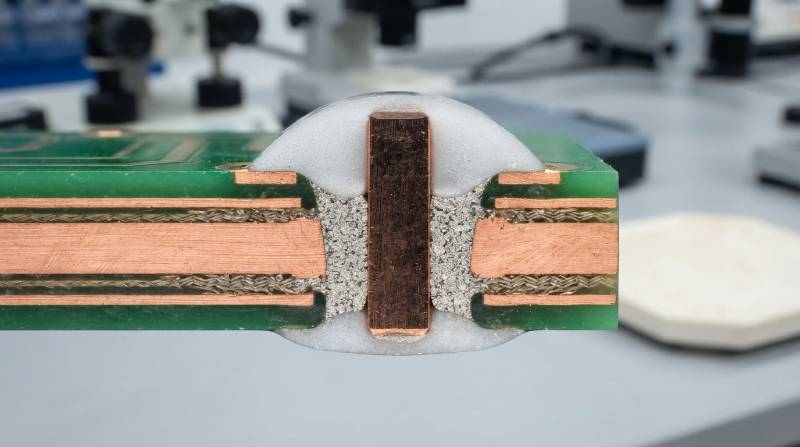
DFM Component Clearance Guidelines: Preventing AOI Shadowing and Solder Bridging
Careful physical spacing between surface-mount footprints and through-hole pin fields is essential for mixed-technology PCBA manufacturability.
Manufacturing Clearance and Geometry Rules
- Keep-Out Distance for Selective Solder Nozzles: Maintain a minimum clearance of 3.0 mm (preferably 5.0 mm) between through-hole pin pads and adjacent bottom-side SMT components. This prevents the selective solder mini-wave nozzle from desoldering nearby passives.
- 3D AOI Inspection Clearances: Place tall DIP components (electrolytic capacitors, power inductors, relays) at least 3.0 mm away from fine-pitch SMT ICs. Tall components cast optical shadows that block the side cameras of 3D AOI inspection systems.
- Hole-to-Lead Aspect Ratios: Per IPC-2222 Class 2 and Class 3 guidelines, the nominal finished through-hole diameter (dh) must equal the component lead diameter or diagonal (dlead) plus 0.20 mm to 0.30 mm:dh = dlead + 0.25 mm (nominal)
- Thermal Relief Geometry: When connecting through-hole pins to internal power and ground planes, use 4-spoke thermal relief patterns with web widths of 0.25 mm to 0.40 mm. Solid copper plane connections act as heat sinks, causing cold solder joints and incomplete barrel fill.
Selective Soldering vs. Wave Soldering vs. Hand Soldering: Technical and Economic Trade-offs
Choosing the right through-hole assembly method directly impacts tooling costs, turnaround speed, and joint reliability. Evaluate our through-hole DIP assembly capabilities to align the best soldering technique with your batch size.| Parameter | Selective Wave Soldering | Standard Wave Soldering | Precision Hand Soldering |
|---|---|---|---|
| Tooling / Fixture Cost | $0 (Software programmed) | $350 – $800 (Pallet/Mask) | $0 |
| NPI Setup Time | 1 – 2 hours | 24 – 48 hours (Tooling fabrication) | Immediate |
| Class 3 Barrel Fill (100%) | Consistent (N2 assisted) | Consistent | Operator-dependent |
| Bottom-Side SMT Risk | Zero (Targeted nozzle path) | High (Pallet masking required) | Zero |
| Best Production Fit | Prototypes & Mid-Volume Runs | High-Volume Uniform Boards | Low-volume harnesses & repair |
Extreme NPI Rapid Prototyping: 24-to-72-Hour Turnaround for High-Density Mixed Boards
Fast-track New Product Introduction (NPI) cycles require compressed assembly timelines without compromising workmanship standards. Complex multi-technology assemblies—such as those pairing 0.35 mm pitch BGAs with heavy-gauge terminal headers—can be assembled and verified within 24 to 72 hours under optimized manufacturing workflows. To hit these tight production windows, our facility runs parallel processing pipelines:- Direct laser stencil direct-machining in-house within 45 minutes of file approval.
- High-speed dual-gantry placement systems loading 01005 passives and large fine-pitch ICs simultaneously.
- Dedicated programmable selective soldering cells running concurrently with bare board production.
- Inline 3D SPI and high-magnification 3D X-ray verification operating in closed-loop feedback loops.
The Visianda 4-Phase Mixed-Tech Fast-Quote & Fabrication Protocol
To eliminate quote revisions and engineering delays, Visianda EMS utilizes an automated verification and manufacturing framework for mixed SMT and DIP assemblies. Opting for full turnkey PCB assembly lets your team hand off procurement, fabrication, and assembly to a single unified workflow.The Four Execution Phases
- Phase 1: Automated BOM & Centroid Scrub — Algorithmic parsing cross-references MPNs against franchised inventories to verify lifecycle status, packaging tape/reel pitch, and rotation orientation within minutes.
- Phase 2: Algorithmic DFM/DFA Verification — Design rule engines check annular rings, barrel-to-lead ratios, solder mask dams (minimum 0.10 mm), and nozzle keep-outs to prevent assembly-line holds.
- Phase 3: Synchronous Fabrication & Franchised Procurement — Bare PCB etching and component kitting run concurrently, supported by 100% Certificate of Conformance (CoC) guarantees from authorized franchised distributors.
- Phase 4: SMT Reflow, Selective Soldering & Closed-Loop Inspection — Production proceeds under calibrated SAC305 profiles, followed by 3D SPI, 3D AOI, and 3D X-ray inspection (confirming BGA voiding ≤ 15%).
Supply Chain Assurance: Transparent Drop-In Replacements & Anti-Counterfeit Verification
Component availability challenges can derail tight development timelines. We maintain direct API integrations with authorized global distributors (DigiKey, Mouser, Arrow, Element14) to monitor real-time stock levels, pricing, and factory lead times. If an active through-hole or SMT component is obsolete or out of stock, our component engineering team recommends Form-Fit-Function (FFF) drop-in replacements. Every recommended alternate undergoes parametric cross-matching (pinout arrangement, thermal dissipation limits, breakdown voltages, and packaging dimensions) and requires explicit customer engineering approval prior to order release. All incoming materials pass strict anti-counterfeit receiving inspections, including high-power optical microscopy, pin-lead tinning verification, and packaging moisture-barrier inspections (per J-STD-033 standards).Frequently Asked Questions on Quick-Turn SMT & DIP Mixed PCBA Quotes
How fast can Visianda EMS return a formal mixed-technology PCBA quote?
When provided with complete Gerber RS-274X/ODB++ files, Centroid (CPL) data, and a multi-column BOM with explicit MPNs, our engineering team generates a line-item verified quote with integrated DFM feedback within 2 hours.Does selective soldering require dedicated tooling or NPI fixture charges?
No. Programmable selective soldering uses robotic coordinate systems and localized mini-wave nozzles, eliminating the $350 to $800 tooling charges and 48-hour fabrication delays associated with wave solder pallets.What is the maximum allowable BGA voiding percentage for mixed assemblies?
While IPC-A-610 Class 2 allows up to 25% total BGA solder ball voiding, Visianda EMS maintains voiding levels strictly below 15% (and < 10% for mission-critical Class 3 builds) using optimized vacuum reflow and high-resolution 3D X-ray inspection.Is full-turnkey assembly faster than customer-consigned (kitted) assembly?
Full-turnkey sourcing typically cuts overall prototype lead times by 40%. It allows bare board fabrication and component sourcing to proceed concurrently, while eliminating shipping delays, kitting count mismatches, and component re-reeling issues.What is the Minimum Order Quantity (MOQ) for quick-turn prototype runs?
We have no minimum order quantity. We support rapid prototype runs starting at 1 to 5 boards, scaling smoothly up to high-volume production batches.How to Secure Your 2-Hour Verified Mixed PCBA Quote with Visianda EMS
Get your project moving from schematic capture to fully assembled, inspected hardware in three straightforward steps:- Export Your Design Package: Compile your Gerber RS-274X / ODB++ archives, Pick-and-Place Centroid coordinates, and standardized Excel/CSV BOM with exact MPNs.
- Upload to the Portal: Submit your files through our online portal to get an instant online PCBA quote and initiate automated DFM scrubbing.
- Receive Your Verified Quotation: Review a line-item quotation detailing component sourcing costs, board fabrication rates, DFM review notes, and guaranteed delivery schedules.
Accelerate Your Mixed-Technology Assembly Pipeline
Leverage fast-track SMT pick-and-place lines, programmable selective soldering, and certified IPC Class 3 quality controls for your next prototype build.
Request Your Mixed PCBA Quote