
The 4 Essential Engineering Files Required for an Accurate PCBA RFQ
To request an accurate ISO-certified PCB assembly quote, submit a complete engineering data package containing bare-board fabrication files (Gerber RS-274X or ODB++), a machine-readable Bill of Materials (BOM) with exact Manufacturer Part Numbers, Pick-and-Place Centroid (XY) coordinates, and explicit assembly and test directives. Delivering these four datasets allows contract electronics manufacturers to calculate exact surface mount technology (SMT) cycle times, component costs, and production tooling without engineering holds. Incomplete Request for Quotation (RFQ) packages cause over 68% of commercial quoting delays across the electronics manufacturing services (EMS) industry. When data is missing, quotation engineers must make assumptions regarding solder mask clearances, component footprints, or board stackups, leading to revised quotes, inaccurate lead times, and downstream manufacturing defects.
Bare Board Fabrication Data: Gerber RS-274X vs. ODB++
Bare board fabrication files define the physical geometry, copper traces, drill locations, and surface finishes of the PCB substrate. While legacy Gerber RS-274X formats remain common, they require separate files for drills, board outlines, and layer stacks, leaving room for manual interpretation errors. Modern data exchange formats like ODB++ and IPC-2581 combine CAD layout, schematic netlists, layer stackups, and component centroid data into a single unified directory. Using ODB++ reduces engineering interpretation errors by over 40% during front-end automated Design for Manufacturability (DFM) verification.- Gerber RS-274X Deliverables: Must include all copper layers, top/bottom solder masks, top/bottom silkscreens, solder paste stencils, NC Excellon drill files, and a documented mechanical fabrication drawing specifying IPC-4552 ENIG or immersion silver finishes.
- ODB++ / IPC-2581 Deliverables: Deliver the complete, uncompressed database export directly from your ECAD tool (Altium, KiCad, Cadence Allegro, or Mentor Xpedition).
Standardized Turnkey BOM Architecture & Approved Vendor Lists (AVL)
A structured Bill of Materials is the single most critical asset for estimating component procurement lead times and turnkey assembly costs. Your BOM spreadsheet must provide granular part descriptions to avoid procurement ambiguities during automated sourcing runs. For seamless pricing, leverage Turnkey PCB assembly solutions that automatically match your lines against authorized franchised inventory databases.| Column Header | Example Entry | Technical Purpose |
|---|---|---|
| Item Number | 1, 2, 3... | Line-item index for automated ERP parsing. |
| Reference Designator | C12, C15, R3, U1 | Maps component placement to PCB coordinate space. |
| Quantity Per Board | 4 | Total instances per individual PCBA unit. |
| Primary MPN | STM32H743ZIT6 | Exact manufacturer part number including packaging suffixes. |
| Primary Manufacturer | STMicroelectronics | Original Component Manufacturer (OCM). |
| Approved Alternates (AVL) | Yageo RC0402JR-0710KL | Drop-in pin-compatible alternates to avoid single-source lead time delays. |
| Package / Footprint | LQFP-144 / 0402 | SMT feeder setup verification and nozzle selection. |
| Installation Type | SMT / THT / DNP | Identifies machine pick-and-place vs. selective solder lines (Do Not Populate). |
Centroid XY Coordinates and Comprehensive Assembly Drawings
The Centroid file (also known as the Pick-and-Place or XY data file) guides the automated high-speed SMT placement machinery. It must include the Reference Designator, X and Y coordinate offsets from the board origin (0,0), Board Side (Top or Bottom), and Component Rotation in degrees (0° to 359°). Assembly drawings complement centroid data by providing explicit mechanical instructions. They illustrate component polarity (diodes, polarized tantalum capacitors, QFN pin-1 orientations), conformal coating keep-out zones, secondary mechanical hardware (heat sinks, standoffs), and through-hole pin trimming limits.Firmware Flashing, Programming, and Functional Testing (FCT) Directives
End-to-end turnkey quotes require explicit testing specifications to account for engineering technician time and custom bed-of-nails test fixture non-recurring engineering (NRE) costs. Provide test coverage requirements during RFQ submission, specifying In-Circuit Testing (ICT), Boundary Scan/JTAG testing, or custom Functional Circuit Testing (FCT). Detail MCU flashing hex files, test point grid pitches (preferably ≥ 1.00 mm for robust pogo-pin contact), expected voltage/current draw tolerances, and pass/fail execution scripts.The Visianda EMS 5-Point Precision Quoting Protocol
To eliminate quote volatility and lead-time inaccuracies, Visianda EMS operates under the 5-Point Precision Quoting Protocol. This systematic engineering review ensures every variable affecting pricing, manufacturability, and quality standards is accounted for prior to contract validation.Methodology Definition: The 5-Point Precision Quoting Protocol is a deterministic, five-stage engineering audit process that validates physical PCB fabrication tolerances, component lifecycle availability, authorized distributor chain-of-custody, IPC quality classifications, and production tooling requirements prior to issuing a fixed commercial quotation.
- Automated BOM Parsing & Lifecycle Scrubbing: Ingests the customer BOM to instantly detect End-of-Life (EOL), Not Recommended for New Designs (NRND), and obsolete components. It cross-references franchised inventory feeds to flag factory lead times exceeding 16 weeks.
- Front-End DFM & DFA Clearance Review: Conducts an automated and manual Design for Assembly (DFA) audit using Comprehensive DFM review services to identify tombstoning risks, solder bridging hazards, high component density shadow effects during reflow, and aspect ratio drill limits.
- Authorized Franchise Sourcing & Traceability Verification: Enforces procurement exclusively through OCM-authorized distributors (e.g., Arrow, DigiKey, Mouser, Avnet), eliminating unauthorized secondary broker risks.
- Standard Quality Benchmarking (IPC Class 2 vs. Class 3): Assesses specific assembly requirements against IPC-A-610 standard specifications, calculating the precise inspection coverage (AOI, 3D X-Ray, manual microscope verification) required for commercial, medical, or aerospace end-use.
- Transparent NRE & Stencil Tooling Structuring: Breaks down all one-time fees, such as laser-cut electro-polished SMT stencils, ICT test fixtures, selective wave soldering pallets, and custom packaging, ensuring zero hidden fees during production handoff.
Major PCBA Cost Drivers and Design Optimization Strategies
Electronics manufacturing pricing is dictated by substrate complexity, component technology, assembly line cycle time, and procurement channels. Understanding these levers allows engineering teams to optimize layouts before freezing designs.PCB Substrate Complexity, Layer Count, and Material Selection
Bare board fabrication costs scale non-linearly with layer count and specialty materials. Standard 4-to-8 layer boards utilizing standard FR-4 (Tg 140°C–150°C) represent the baseline cost structure. High-Density Interconnect (HDI) boards with microvias, sequential lamination cycles, heavy copper weights (> 2 oz), or high-frequency Rogers/PTFE substrates increase fabrication costs by 30% to 150%. Specifying High-Tg FR-4 (Tg ≥ 170°C) provides optimal thermal stability during lead-free SAC305 reflow profiles (peaking at 245°C–255°C) without incurring extreme exotic substrate penalties.SMT Component Density: Fine-Pitch ICs, BGAs, and Through-Hole DIP
SMT placement machine throughput is measured in components per hour (CPH). Small passive devices (0402, 0603) place rapidly, whereas micro-BGAs (pitch < 0.4 mm), Quad Flat No-Lead (QFN) packages with exposed thermal pads, and 01005 passives require specialized visual feeder calibration and reduced placement speeds.- Through-Hole Soldering Operations: Manual hand soldering or selective wave soldering of Dual In-line Package (DIP) components requires dedicated labor and custom titanium soldering pallets, increasing per-joint assembly costs by 3x to 5x compared to automated SMT joints.
- Double-Sided SMT Assembly: Placing active ICs on both the top and bottom layers requires two distinct solder paste printing, pick-and-place, and reflow passes, which increases setup time and stencil NRE costs.
Procurement Strategy: Full Turnkey vs. Consigned Components
Choosing between turnkey sourcing and consigned (kitted) parts significantly affects administrative overhead and project risk.| Evaluation Vector | Full Turnkey Manufacturing | Consigned / Kitted Sourcing |
|---|---|---|
| Component Sourcing | Handled entirely by EMS via franchised distributors. | Procured and kit-packed internally by the customer. |
| Attrition & Scrap Risk | EMS manages attrition buffers (typically +1% to +5% passives). | Customer must supply extra components for SMT machine setup waste. |
| Traceability & CoC | Guaranteed factory Certificates of Conformance (CoC) provided. | Customer assumes legal liability for component authenticity. |
| Logistics Overhead | Single consolidated shipping point and invoicing workflow. | Multiple inbound freight costs, customs duties, and kit delays. |
Evaluating ISO-Certified Contract Manufacturing Standards & Traceability
Not all electronics manufacturing services providers operate with the same quality standards. Requesting a quote from an ISO-certified facility ensures your assemblies meet standardized process control benchmarks established under international regulatory frameworks. When requesting quotes, verify factory certifications according to your product application requirements using our verified ISO quality and inspection standards:- ISO 9001:2015: The universal quality management baseline for industrial and consumer electronics, audited per ISO 9001:2015 quality management benchmarks.
- ISO 13485:2016: Mandatory quality management system for medical device assemblies, enforcing sterile handling, process validation, and device master record (DMR) archiving.
- IATF 16949:2016: Strict automotive standard governing failure mode effects analysis (FMEA), PPAP submissions, and zero-defect quality thresholds.
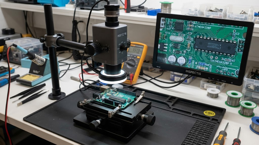
Quality Verification: IQC, Automated Optical Inspection (AOI), and X-Ray
An ISO-certified quote includes standard non-destructive testing and optical inspection checkpoints embedded into the baseline pricing:- Incoming Quality Control (IQC): Component verification against packaging slips, checking moisture barrier bags (MBB) and humidity indicator cards (HIC).
- 3D Solder Paste Inspection (SPI): Inline measurement of solder paste volume, height, and alignment directly after stencil printing to prevent 70% of downstream soldering defects.
- Automated Optical Inspection (AOI): High-speed multi-angle optical checks for component presence, skew, polarity, wrong markings, and solder fillets.
- 3D Automated X-Ray Inspection (AXI): Essential for hidden joint packages (BGAs, QFNs, LGAs) to verify solder ball collapse, bridge defects, and void percentages (ensuring < 15%–25% void area in compliance with IPC Class 3).
- First Article Inspection (FAI): Complete engineering verification of the first assembled unit against CAD netlists before launching mass SMT production runs.
Supply Chain Integrity: Anti-Counterfeiting and Full Component Traceability
Counterfeit electronic components present catastrophic operational risks. ISO-certified contract manufacturers maintain stringent lot traceability and component chain-of-custody protocols. Every active reel, tray, or tube is tagged with unique internal UID tracking barcodes upon factory arrival. Moisture-Sensitive Devices (MSD) are tracked and baked in strict accordance with IPC/JEDEC J-STD-033 standards to prevent popcorning defects during reflow. Certificates of Conformance (CoC) and manufacturer date code logs are archived for a minimum of 3 to 10 years depending on ISO regulatory mandates.Step-by-Step Guide: How to Submit Your RFQ to Visianda EMS for Fast Quoting
Follow this checklist to generate a complete, audit-ready engineering RFQ package for your next prototype or volume production run.
- Package Your ECAD Data: Export your bare PCB layout files (Gerber RS-274X with drill charts or complete ODB++ folder). Ensure board outlines and cutouts are clearly defined on the mechanical layer.
- Structure Your BOM: Organize your component list in `.xlsx` or `.csv` format. Ensure every active part includes a complete, un-truncated MPN, Primary Manufacturer, Footprint, and Reference Designators matching the CAD files.
- Export Centroid (XY) Data: Generate the Pick-and-Place text file containing reference designators, X/Y coordinates in millimeters or inches, rotation angles, and top/bottom board assignment.
- Define Production Parameters: Determine your delivery targets:
- Quick-turn prototype run (24–72 hour assembly turnaround).
- Pilot run (100–1,000 units) for design verification testing (DVT/PVT).
- Scheduled blanket production releases for high-volume manufacturing.
- Attach Testing & Mechanical Directives: Include functional test instructions, programming firmware hex files, conformal coating drawings, and custom packaging requirements (e.g., ESD shielding bags, partitioned cell boxes).
- Upload to Quote Portal: Submit your compressed `.zip` package via our secure Instant PCBA quote request portal to receive a detailed, line-item engineering quotation and preliminary DFM report.
Frequently Asked Questions About ISO-Certified PCBA Quoting
What is the typical turnaround time for a turnkey PCBA quotation?
Standard turnkey PCBA quotations are delivered within 24 to 48 hours for standard builds. Highly complex designs involving custom functional test fixture fabrication, exotic Rogers substrates, or hard-to-find components requiring multi-distributor sourcing audits may require 3 to 5 business days.What do Non-Recurring Engineering (NRE) tooling charges cover?
NRE charges are one-time fees incurred during initial production setup. These cover high-precision laser-cut stainless steel SMT stencils, automated pick-and-place machine feeder programming, optical AOI/AXI inspection program generation, and custom wave soldering pallets or ICT test fixtures.How does Visianda EMS handle component obsolescence and supply chain shortages?
Our quotation team runs automated lifecycle scrubbing during the RFQ review. If an MPN is flagged as obsolete or out of stock across franchised distributors, our engineering team suggests drop-in pin-compatible alternates from our Approved Vendor List (AVL) for customer sign-off prior to procurement.How is intellectual property (IP) and design firmware protected during the quote and build process?
All design files, Gerber data, and proprietary firmware flashing images are protected under legally binding Non-Disclosure Agreements (NDAs). Design databases are stored on secure, encrypted internal servers with role-based access controls, ensuring strict IP security throughout manufacturing.Ready to Accelerate Your PCBA Production?
Submit your Gerber files and BOM today. Receive a comprehensive, transparent DFM review and an ISO 9001/13485-certified turnkey quotation from the Visianda EMS engineering team within 24 hours.
Request Your Precision PCBA Quote