
Turnkey Box Build Assembly Services: Complete Electro-Mechanical System Integration
Turnkey box build assembly delivers complete, fully integrated electro-mechanical systems directly to market by consolidating raw component procurement, board fabrication, precision housing manufacturing, harness routing, and automated validation under a single production ecosystem. This unified approach eliminates vendor friction, shortens lead times, and enforces end-to-end quality standards across the entire product build.
- Level 3 (Sub-Assembly Integration): Mounting completed PCBAs into structural sub-chassis, integrating internal heat spreaders, and mating sub-tier daughter cards.
- Level 4 (Full Electro-Mechanical Assembly): Complete integration of custom wire harnesses, power supplies, human-machine interfaces (HMI), displays, machined metal or molded plastic enclosures, and environmental gaskets.
- Level 5 (Shelf-Ready Fulfillment): Final serialized assembly including cryptographic security provisioning, custom retail packaging, regulatory documentation, and direct drop-ship distribution.
The Box Build Integration Matrix: Evaluating True Turnkey vs. Split-Vendor Models
Hardware procurement teams frequently face the structural choice between fragmented multi-vendor models and unified turnkey contract manufacturing. When managing separate vendors for PCBA fabrication, sheet metal stamping, injection molding, custom cabling, and final integration, operational friction compounds rapidly across the supply chain.
| Evaluation Parameter | Split-Vendor Consignment Model | Visianda Turnkey Box Build Model |
|---|---|---|
| Tolerance Stack-Up Ownership | Fragmented; shared blame between PCBA and mechanical fabricators | Single-source ownership; verified via pre-production 3D DFA simulation |
| Logistics & Handling Overhead | High freight costs across 3-5 distinct fabrication sites | Optimized; reduced logistics and handling costs by up to 35% |
| NPI Engineering Lead Time | 10-14 weeks due to cross-vendor alignment loops | 6-8 weeks via synchronized in-house fabrication cells |
| End-of-Line Quality Verification | Limited to board-level testing; chassis fit unverified until final stage | 100% automated system-level functional test (FCT) and safety validation |
Total Cost of Ownership (TCO) Principle: Sourcing piece-part components from the lowest-bid vendors frequently increases landed unit costs by 18% to 27% once freight charges, internal quality audits, buffer stock, and assembly re-work hours are accounted for in production.
Precision Engineering & Design for Assembly (DFA) Stack-Up Analysis
Precision electro-mechanical manufacturing requires strict alignment between mechanical housings and internal electronics. Board warping, thermal expansion mismatches, and mechanical tolerance accumulation can introduce structural strain onto surface-mount solder joints, resulting in premature field failures. Our engineering team applies rigid Design for Assembly (DFA) verification during the early New Product Introduction (NPI) stage. We simulate physical fit-up using 3D CAD modeling, verifying thermal expansion coefficients (CTE) between FR-4 circuit boards (typically 14 to 17 ppm/°C along the X/Y axes) and aluminum 6061 or sheet metal housings (23 ppm/°C). This ensures that mounting points maintain tight tolerances of ±0.05 mm across the entire industrial operating range of -40°C to +85°C. Critical mechanical mounting rules implemented during DFA stack-up include:- Clearance Optimization: Maintaining a minimum of 1.5 mm keep-out distance between SMT passive components and mounting screw heads to prevent trace fracturing during high-vibration operation.
- Standoff Placement: Balancing mechanical standoffs around heavy magnetic components, chokes, and large power inductors to eliminate resonant board deflection during transit.
- Thread-Locking Chemistry: Applying pre-applied microencapsulated or automated post-assembly thread-locking adhesives (compliant with ASTM D5363) to prevent fastener back-out under continuous vibration.
Subsystem Integration: Wire Harnesses, Thermal Management, and Environmental Sealing
A reliable box build requires clean subsystem execution. Routing internal interconnects, dissipating localized heat, and preventing ingress of moisture or particulate matter represent the mechanical backbone of rugged electronics.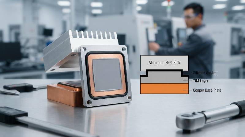
Extreme Scenario Benchmark: High-Reliability Industrial IoT & Class II/III Medical Box Builds
Mission-critical systems operate under severe environmental, electrical, and regulatory demands. Whether manufacturing an edge AI computing gateway exposed to industrial electrical surges or a Class II/III medical diagnostic system, manufacturing defects can lead to costly downtime or safety hazards. Visianda EMS manufactures complex electro-mechanical assemblies requiring fine-pitch surface-mount assembly—supporting 01005 passives and 0.35 mm pitch micro-BGAs—integrated alongside high-power industrial switching circuits. In our cleanroom assembly facilities, technicians follow rigorous Electrostatic Discharge (ESD) controls conforming to ANSI/ESD S20.20-2021. Key regulatory and technical capabilities for specialized box builds include:- Medical Systems (ISO 13485:2016 Certified): Biocompatible enclosure assembly, cleanroom sub-assembly integration, fully validated risk mitigation files, and rigorous lot-level traceability down to raw component wafer runs.
- Industrial Edge & Automotive (IATF 16949 / IPC-A-610 Class 3): Ruggedized aluminum die-cast housings, internal RF co-axial cable routing with controlled bend radii to prevent impedance mismatches, and vibration-isolated board mounting.
- Optical and Sensor Calibration: Precision multi-axis alignment jigs ensuring high-precision positioning of laser diodes, CMOS image sensors, and LiDAR lenses within ±20 µm.
The Visianda 5-Tier Verification Protocol: Automated EOL & Electrical Safety Validation
To eliminate early-life field failures, Visianda EMS implements a proprietary validation methodology for every production unit: The Visianda 5-Tier Verification Protocol. This multi-stage process verifies structural integrity, board assembly, and system operation before shipment.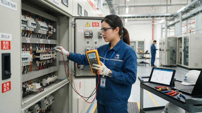
- Tier 1: In-Circuit Testing (ICT) & Boundary Scan (JTAG): Automated bed-of-nails and JTAG boundary scan testing validates passive component tolerances, detects open circuits, and verifies that BGA balls are fully connected with zero micro-bridging.
- Tier 2: Dielectric Withstand (Hi-Pot) & Insulation Testing: High-voltage dielectric testing up to 5 kV AC/DC ensures clear galvanically isolated physical spacing. Insulation resistance testing verifies values > 100 MΩ at 500 V DC.
- Tier 3: Ground Continuity & Protective Bonding: High-current ground bond testing (applying 25 A to 32 A AC) verifies that chassis grounding paths maintain a resistance of < 0.1 Ω, complying with IEC/EN 61010-1 and IEC 60601-1 safety mandates.
- Tier 4: Automated End-of-Line Functional Testing (ATE): Custom rack-mounted automated test equipment exercises all digital I/O, analog signals, serial communication protocols (CAN-FD, RS-485, Ethernet, USB 3.2), and wireless interfaces in an isolated RF Faraday chamber. Explore our end-of-line functional testing solutions for complex systems.
- Tier 5: Environmental Stress Screening (ESS) & Burn-In: Units run live functional firmware under full electrical load within thermal chambers cycling from -40°C to +85°C over extended stress durations (typically 12 to 72 hours) to trigger early component mortality before shipment.
Firmware Provisioning, Secure Key Injection, and Unit Traceability Workflows
Complete box build integration extends beyond mechanical assembly to automated device provisioning. Every connected IoT device, medical instrument, and industrial controller requires secure, unique cryptographic identity injection prior to packaging. Our turnkey workflows support modern silicon security architectures:- Secure Hardware Root-of-Trust (RoT): Direct injection of elliptic-curve private keys, asymmetric certificates, and custom bootloaders into secure elements (e.g., ATECC608, TPM 2.0 modules, or secure MCU enclaves) within an isolated air-gapped network.
- Production Firmware Flashing: High-speed parallel gang programming with automated cyclic redundancy check (CRC32 / SHA-256) validation to verify flash integrity.
- Laser-Etched Traceability: High-density 2D DataMatrix or QR serialization laser-etched onto the mechanical chassis, permanently binding the PCB MAC address, SMT production batch, raw silicon lots, test operator ID, and final functional test log to our secure MES database.
Comparative Analysis: Turnkey Box Build vs. In-House Final Assembly
Deciding between internal electro-mechanical assembly and an outsourced turnkey EMS model is a primary operational inflection point for scaling hardware companies. Evaluating the true operational expenses clarifies this decision.| Operational Dimension | In-House Final Box Assembly | Visianda Turnkey Box Build Services |
|---|---|---|
| Capital Equipment Expenditure | High (150k -500k+ for ESD lines, torque stations, test racks, thermal chambers) | Zero CapEx; leverage existing fully depreciated, enterprise-grade facilities |
| Production Labor Scaling | Fixed direct overhead; requires hiring, training, and managing assembly line operators | Fully variable cost structure; scales elastically from 50 prototype units to 100k+ mass runs |
| Supply Chain Complexity | High; internal procurement handles 100+ line items, custom fasteners, and packaging | Single consolidated line item with end-to-end component procurement and kitting |
| Quality Certifications | Requires dedicated continuous audits for ISO 9001, ISO 13485, and IATF 16949 | Fully certified production lines audited by global registrars |
Frequently Asked Questions About Turnkey Box Build Services
What file formats are required for a complete turnkey box build quote?
To provide an accurate, fixed-price turnkey quotation, our engineering team requires:- 3D mechanical assembly models in STEP, IGES, or native SolidWorks/Parasolid format.
- PCB fabrication and assembly data (Gerber RS-274X or ODB++, centroid/pick-and-place files).
- Consolidated Bill of Materials (BOM) including manufacturer part numbers, designated approved alternate sources, and mechanical hardware specifications.
- Wire harness schematic drawings, pinouts, and cable length dimensions.
- Detailed Functional Test Specifications (FTS) and firmware flashing procedures.