
Kingdta manufactures custom flexible printed circuits (FPC) for hardware teams worldwide. From single-layer flex for simple interconnects to complex multilayer rigid-flex designs, our engineering team supports your project from DFM review through production.
What Is a Flexible PCB (FPC)?
A flexible printed circuit (FPC) is a type of printed circuit board manufactured on a flexible substrate — typically polyimide (PI) or polyester (PET) — allowing the circuit to bend, fold, or conform to three-dimensional shapes. FPCs are widely used where space constraints, weight reduction, or dynamic flexing are design requirements.
Compared to rigid PCBs, FPCs offer significant advantages in miniaturized products: they can replace wire harnesses, reduce connector count, and enable compact packaging in wearables, medical devices, cameras, and consumer electronics.
Kingdta produces single-sided, double-sided, and multilayer FPC with coverlay protection, stiffener reinforcement, and EMI shielding options. Our minimum trace width is 0.1mm (4 mil) with 0.1mm spacing.
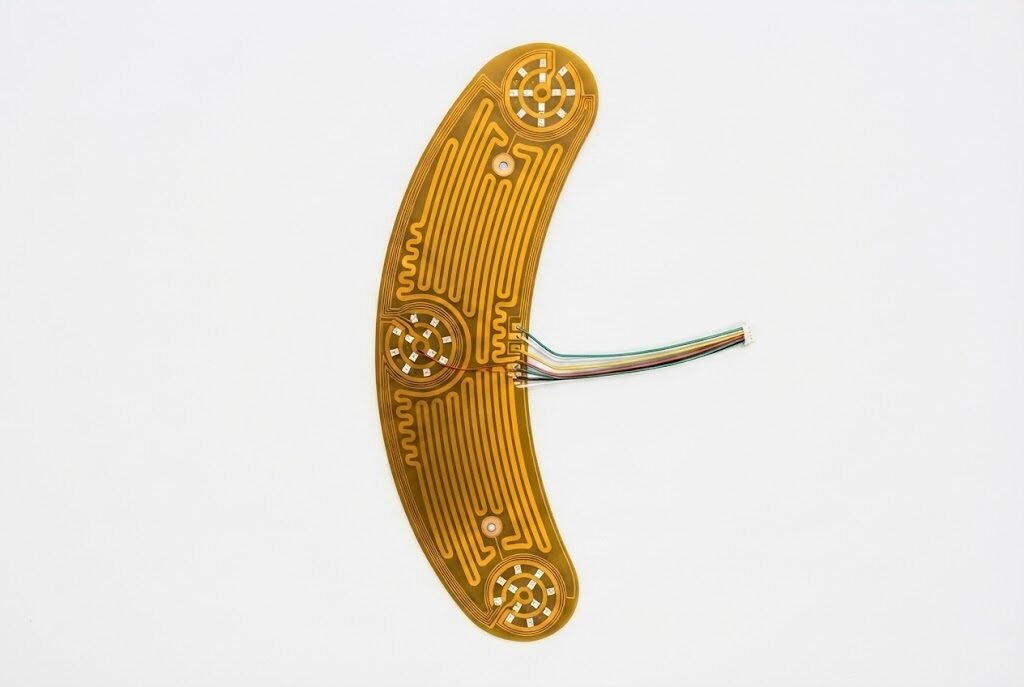
Technical Specifications
Key Advantages
Space & Weight Savings
FPCs replace bulky wire harnesses and reduce overall product weight by up to 70% in compact assemblies.
Dynamic Flexing Capability
Engineered for millions of flex cycles — ideal for hinges, fold mechanisms, and moving parts.
3D Packaging Freedom
Fold and route circuits in three dimensions, enabling designs impossible with rigid PCBs.
Reduced Assembly Errors
Eliminates individual wire connections, reducing assembly time and connection errors.
Excellent Thermal Performance
Thin polyimide substrate dissipates heat efficiently in high-density assemblies.
EMI Shielding Options
Integrated copper or conductive adhesive shielding layers available for RF-sensitive applications.
Where It's Used
Wearables
Smartwatches, fitness trackers, AR glasses
Medical Devices
Endoscopes, hearing aids, implantable sensors
Consumer Electronics
Smartphones, laptops, cameras, drones
Automotive
Dashboard displays, steering wheel controls
Industrial
Robotic joints, inspection equipment
IoT Devices
Smart home sensors, wireless modules
Aerospace
Satellite components, avionics
LED Lighting
Flexible LED strips, curved displays
Why Choose Kingdta for Flexible PCB?
- ISO 9001:2015 certified FPC manufacturing with IPC-A-600 inspection standards
- Free DFM analysis on every order — we catch flex circuit design issues before production
- Minimum order from 1 piece — ideal for prototyping and small batch production
- Full turnkey service: FPC fabrication + SMT assembly + functional testing in one order
- Experienced engineering team with 10+ years in flexible circuit manufacturing
- MES traceability system records every production step for quality accountability
Frequently Asked Questions
What is the minimum bend radius for your FPC?
Our standard minimum bend radius is 6× the total board thickness for static applications and 10× for dynamic flexing applications. We can optimize the stackup for your specific flex requirements.
Can you assemble SMT components on FPC?
Yes. We assemble SMT components on FPC using custom fixtures to maintain flatness during reflow. We handle 0201 passives, fine-pitch ICs, and connectors on flexible substrates.
What stiffener options are available?
We offer PI, FR4, stainless steel, and aluminum stiffeners. Stiffeners are applied in areas requiring rigidity — typically connector zones and component mounting areas.
Do you offer FPC with ZIF connectors?
Yes. We can design and manufacture FPC with ZIF (zero insertion force) connector tails, including gold plating on the contact fingers for reliable mating.
Related PCB & PCBA Types
Solving FPC Delamination in a Continuous Glucose Monitor
A UK-based medical device startup developing a disposable continuous glucose monitor (CGM) patch — worn on the upper arm for 14 days with 5-minute reading intervals.
The Problem
The customer's previous FPC supplier delivered boards with coverlay delamination at the flex zone after fewer than 200 flex cycles in accelerated life testing — far below the 50,000-cycle requirement for the 14-day wear period. The root cause was inadequate adhesive coverage at the coverlay-to-copper interface in the dynamic flex zone.
Key Challenges
- Dynamic flex zone required 50,000+ cycles at 180° bend with 3mm bend radius
- Polyimide substrate thickness needed to be ≤0.1mm to maintain patch conformability
- SMT pads for a 0.4mm pitch BLE SoC adjacent to the flex zone
- ISO 13485 documentation requirements for a Class II medical device
- 8-week timeline to production-ready samples for regulatory submission
Our Solution
Our FPC engineering team performed a full DFM review and identified three root causes: insufficient adhesive dwell time during coverlay lamination, incorrect coverlay window sizing leaving exposed copper at the bend initiation point, and a copper trace routing pattern that concentrated stress at a single point. We redesigned the flex zone with teardrop trace terminations, increased the coverlay overlap to 0.3mm beyond the pad edges, and implemented a two-stage lamination cycle with extended dwell at 170°C. We also added a 0.05mm PI stiffener transition zone at the rigid-to-flex boundary to distribute bending stress. All process parameters were documented in an IQ/OQ/PQ validation package for the customer's regulatory file.
Results & Outcomes
"Kingdta's engineering team didn't just build what we sent them — they identified the root cause of our delamination issue that two other suppliers had missed. The DFM report was detailed enough to include in our design history file. We've been working with them for three product generations."
Hardware Lead, Medical Device Startup — Cambridge, UK